Products || Above & Below Sink
Undersink Water Chiller
mini Boil 'n chill Installation & Maintenance
Installation & Maintenance:
MC series Below Sink Chiller
- Please note: if supply cord is damaged – it must be replaced by the manufacturer, it’s service agent or similarly qualified persons in order to avoid a hazard.
- This appliance is not intended for use by persons(including children) with reduced physical, sensory or mental capabilities, or lack of experience and knowledge, unless they have been given supervision or instruction concerning use of the appliance by a person responsible for their safety.
- Children shall be supervised to ensure that they do not play with the appliance.
- Unit is not to be installed for outdoor use.
- This appliance can only be disconnected from the power supply by unplugging it from the wall socket. Make sure the plug and socket are readily accessible.
- Minimum Working Pressure – 200Kpa
- Maximum Working Pressure – 800Kpa
ideal working temperature is between 2°c - 30°c to prevent freezing, if freezing does occur turn unit off immediately.
If fitted with filter we recommend changing the cartridge every 6 months.
The manufacturer recommends the cleaning and service of the unit every 12 months.
Installation instructions – model MC series
Do not plug in or turn on power
- This unit to be installed underneath a kitchen sink in a cabinet not less than 700mm wide. A vent should be installed in the door adjacent to the fan aperture or alternatively have an air vent in toe space and one above near top of door. The remote unit must have 25mm at front and back of the unit, the unit can be installed flush against either side wall of the cabinet. Objects located within 100mm of slots must not block the side slots, which are not against the cabinet.
- The unit shall be installed on a level surface. (Do not allow the unit to be tilted in installation!)
- Water inlet and outlet ¼ diameter tubes with connectors supplied.
- Ensure connecting lines are thoroughly flushed to remove all foreign matter before connection to cooler.
- Connect cooler to main water supply with a 350kpa pressure-limiting valve fitted with Dual Checks, fit tap as required.
- Plug cooler into appropriate 10-amp main supply. DO NOT TURN POWER ON.
- Open supply valve.
- Purge air from water lines by operating tap to which cooler is connected; steady stream assures all air is removed.
- Turn on power to cooler wait 30 minutes for initial chill cycle.
Precautions:
The plumbing installation must be done in accordance with local water authority regulations and these installation instructions.
The installer must supply (if necessary) and install all valves required by local regulations and/or relevant standards.
Trouble Shooting and Maintenance
Action to be performed by a qualified person.
Temperature control:
Factory set 3 degree c (+2 degree) under normal conditions.
Ventilation:
Cabinet louvers and condenser fins should be periodically cleaned with brush or vacuum cleaned excess dirt etc will result in poor ventilation will cause compressor to overheat resulting in no cold water.
Cleaning:
The coil at the front of the unit must be kept clean. check on a regular basis ie weekly and should be dusted and/or vacuumed.
The vents on the side of the unit should be free from dust or lint and checked on a regular basis.
The cover itself should be wiped over with a damp cloth.
Service:
All maintenance is to be carried out by a qualified and experienced person.
Due to the unit holding r134a gas a plumber, electrician or qualified boiling billy agent is required for all work.
Warranty
Wiffen Products Pty Ltd guarantees your chiller against faulty manufacture or mechanical defect for a period of 12 months from date of installation.
An authorised person in accordance with AS/NZS3500.1 and AS/NZS3500.2 must install the unit.
The warranty is void if unit is modified in any way, misuse, faulty installation, water conditions and unauthorised persons working on the unit.
The warranty does not cover filters.
If unit does not operate correctly, the unit must be sent back to the manufacture’s factory for replacement or repairs to the unit and customer to pay freight both ways.
The company obligation per warranty is limited to repair or replacement of parts at the discretion of the company. (For disclaimer particulars contact manufacturer).
Wiffen Products Pty Ltd reserves the right to amend this warranty or design at any time without notice.
Under Sink Boiling Billy
Undersink TD Series Installation & Maintenance
Installation & Maintenance:
Boiling Billy Undersink TD series.
This undersink BOILING BILLY dispenses BOILING water – Please treat with care.
Do not use the undersink BOILING BILLY for washing hands.
Important: Do not regulate water flow with the tap. Have your plumber install a pressure limiting vale if pressure exceeds manufacturers recommendations (350Kpa).
For areas with pressure above 350 Kpa, an authorised 350 Kpa only pressure limiting valve must be fitted for maximum efficiency.
*Maximum inlet pressure 350 Kpa
*Minimum inlet pressure 250 Kpa
This unit is fitted with a computerised element and boil dry protection. The computer is set at 97°, altitude will alter temperature (refer to manufacturer).
Warning:A backflow prevention device complying with the requirement of A.S. 3500 I is required to be installed on the water supply inlet to this unit.
DO NOT SWITCH ON POWER WITHOUT WATER RUNNING OUT FROM THE TAP.
-
If fitted with filter we recommend changing the cartridge every 6 months
-
The manufacture recommends the cleaning and service of the unit every 12 months
-
IF SUPPLIED CORD IS DAMAGED IT MUST BE REPLACED BY AN AUTHORISED SERVICE AGENT (ELECTRICIAN).
INSTALLATION INSTRUCTIONS
Action to be performed by a qualified person.
Model TD Series Undersink
Do not plug in or turn on power
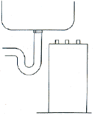
| 1. Position heater unit underneath the sink as close as possible to its outlet tap.
3. OBSERVING THE ATTACHED LABELS
|
4. All pipes and tubes must not be extended and must have a continuous fall between tap and heater. 5. OPEN TAP UNTIL WATER IS FLOWING FROM THE SPOUT. 6. Plug unit into power point and switch on. |
Before using we recommend the fitting of a water filter.
Only Teflon tape to be used where necessary.
Under no circumstances is plumber’s paste to be used.
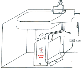
TYPICAL INSTALLATION
N.B. When fitting this unit in a cupboard of small proportions, please note that the unit does omit heat.
If in doubt fit cross flow vents.
DO NOT connect to hot water line – to do so will void warranty.
AFTER POWER IS ON – allow 30 minutes before using.
TROUBLE SHOOTING
Action to be performed by a qualified person.
Undersink TD Series
| SYMPTOM | CAUSES | ACTION |
| No Water
|
Water supply turned off | Check mains supply |
| Blocked filter | ||
| Water not hot
|
Faulty element | Replace element |
| No power supply | Check and test power supply | |
| Water overflowing from tap spout
|
Expansion Chamber full | Run tap for 5-10 minutes |
| Low inlet pressure | Contact Manufacturer | |
| Excessive steam from tap | Faulty element | Replace element |
Mini Boil 'n Chill
Mini Boil 'n Chill Installation & Maintenance
Installation & Maintenance:
MBC series above sink Boiling Billy mini boil n' chill
This unit dispenses boiling water – please treat with care.
If a tundish is to be used, it must be placed in accordance with your plumbing authorities regulations.
If fitted with filter we recommend changing the cartridge every 6 months.
The manufacturer recommends the cleaning and service of the unit every 12 months.
Installation instructions – model MBC series
Do not plug in or turn on power
- Remove four screws from plastic case and remove cover.
- Mount unit on the wall using fixing points on the back of the unit. Unit is to be positioned 300-350mm above a drain board when possible, so that in the event of filling cups, etc. Spillage occurs, water is disposed via sink.
- Connect cold water supply to inlet (12mm) through a stop tap in the supply line. (stop tap to be supplied by the installer). Provision is made for concealed plumbing or out of the bottom of the unit.
- Connect overflow pipe to waste (12mm). Check with plumbing regulations in your state. Do not block the overflow pipe.
- Place plastic cover back onto the unit and secure with the four screws.
- Fit red handle tap onto the left hand side inlet (boiling water) and the black handle tap onto right side inlet (chilled water).
- Plug unit into 10amp power inlet (do not turn on the power).
- Turn 'on' water supply to the unit and 'open' the red handle tap only until water flows out of the tap. If fitted with internal filter flush 18 litres of water through unit.
- When the water flows out of the red handle tap and the chiller tap, please switch the power on.
Allow approx. 30 minutes before use
Only teflon tape to be used where necessary, under no circumstances is plumbers paste to be used.
Do not connect to hot water line – to do so will void warranty.
TROUBLE SHOOTING
Action to be performed by a qualified person.
CHILLED UNIT
| SYMPTOM | CAUSES | ACTION |
| Water overflowing | Water level too high | Check and set approx 20mm. Below the overflow pipe inside the flow tank. Remove ball valve body and Insert, clean and reinstall and Adjust ball valve arm if necessary. Remove ball valve float and Check to ensure that there is no water in it. Replace if necessary. Ensure ball valve closes (does not leak). |
| Not cold | Power not on | Check if power is turned on. |
| Faulty thermostat | Contact service agent or Manufacturer. | |
| Faulty compressor | Contact service agent or Manufacturer. | |
| Loss of Gas | Contact Manufacturer. | |
| Poor ventilation | Clean cabinet louvers (if fitted) and condenser fins (located under fan). The unit must have ventilation. | |
| No water | Water has been turned off | Turn on water. |
| Blocked ball valve | Remove ball valve and clean or replace if necessary. | |
| Blocked filter | Replace if necessary. | |
| Faulty thermostat | Check to ensure that thermostat has not been turned to cold all the way, this will freeze the unit. | |
|
RATING CONDITIONS PERFORMANCE |
||
TROUBLE SHOOTING
Action to be performed by a qualified person.
BOILING WATER UNIT
| SYMPTOM | CAUSES | ACTION |
| Water overflowing | Water level too high | Check and set approx 20mm.Below the overflow pipe inside the flow tank. (Bend arm if necessary) Remove ball valve body and Insert, clean and reinstall. Adjust ball valve arm if necessary. Remove ball valve float and check to ensure that there is no water in it. Replace if necessary. |
| Continuous Boiling | Ball valve defective | Ensure ball valve closes off. |
| Faulty element | Replace element. | |
| Water is not hot | Power not on | Check if power is on. |
| Element Faulty | Replace element. | |
| Water has been turned off | Turn on water. | |
| Blocked ball valve | Remove ball valve and clean out or replace if necessary. | |
| No water | Blocked flow tank (hole) | Remove arm and ball float from the flow tank and using 3mm diam wire clean out the hole situated near the bottom of the flow tank. |
| Blocked filter | Change filter cartridge. |
ULTIMIX
Installation & Maintenance:
UltiMix Series
"ULTIMIX" dispenses BOILING water – Please treat with care.
Do not use the "ULTIMIX" for washing hands
Supply temperature – 5 deg to 35 deg
This unit is fitted with a computerised element and boil dry protection.
Altitude will alter temperature (refer back to manufacturer)
* Rapid action ¼ turn tap handles
* No drainage or overflow is required
* The tap vents through the tap spout
Components supplied with the unit;
-
Chiller unit
-
Boiling water unit
-
Tap dispenser
-
Aquaknect flexible connector – 450mm long (Do not over tighten)
-
Combined dual check valve with 350 Kpa PLV (Connected to boiling water unit)
* If fitted with filter we recommend changing the cartridge every 6 months
* The manufacturer recommends the cleaning and service of the unit every 12 months
* IF SUPPLIED CORD IS DAMAGED IT MUST BE REPLACED BY AN AUTHORISED SERVICE AGENT (ELECTRICIAN).
Installation instructions – model ULTIMIX series
Do not plug in or turn on power - Unit must be positively earthed
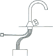
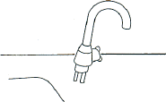
- Position the tap head on a flat area in an appropriate location (i.e. Tea room sink), Drill 38mm diameter hole, washer supplied.
- Position boiling water unit underneath the sink directly beneath the tap head.
- Observe attached labels (ensure when pipes are cut – deburr ends before fitting).
- Connect 5/16” outlet from the tap head spout to the boiling water unit, NB: The pipe must not be extended and must have continuous fall between tap and boiling water unit.
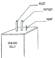
- Connect inlet pipe from the tap body to the boiling water unit (inlet).
- Connect main water supply from the tap body to the outlet side of the filter head.
- Connect the 3/16” nylon tube from the tap to the 3/16” copper vent pipe on the boiling water unit. (heat nylon tube ends in boiling water to ensure easier fitting).
- Position the chiller unit adjacent to the boiling water unit with a minimum clearance between the units of no less than 50mm.
- Connect inlet and outlet pipes from the tap head to chiller unit as per markings.
- Connect aquaknect flexible hose to PLV (inlet side of the filter head).
- Open both taps until the water is flowing from both spouts. 18 litres of water must be flushed through filter before turning on power.
- Plug units into the power point and switch on.
|
TYPICAL INSTALLATION |
|
|
TROUBLE SHOOTING
Action to be performed by a qualified person.
BOILING WATER UNIT
| SYMPTOM | CAUSES | ACTION |
| No Water | Water supply turned off | Check mains supply |
| Blocked Filter | Replace Cartridges | |
| Water not hot | Faulty element and computer | Replace dual computerised element |
| No power supply | Check and test power supply | |
| Water overflowing from tap spout | Expansion chamber full | Run tap for 5 – 10 mins, this will correct water level in expansion tank |
| Low inlet pressure | Contact manufacturer | |
| Boiling On | Replace element | |
| Excessive steam from tap | Fault element | Replace element |
| The boiling water unit is designed to have no less than 150ml off at any one time. | ||
TROUBLE SHOOTING
Action to be performed by a qualified person.
CHILLED UNIT
| SYMPTOM | CAUSES | ACTION |
| No water | Water supply turned off | Check mains supply |
| Blocked Filter | Replace cartridges | |
| Water not cold | Thermostat | Not set correctly |
| Loss of gas | Contact manufacturer | |
| Failed fan | Contact manufacturer | |
| No power supply | Check and test power supply | |
| Poor ventilation | Clean cabinet louvers (if fitted) & condenser fins - these units need ventilation | |
| Faulty element |
Replace element |
Above Sink Boiling Billy
JE & JR Series Installation & JE, JR & SBB Maintenance
Installation & Maintenance:
Boiling Billy JE & JR Series.
The above sink BOILING BILLY dispenses BOILING water - PLEASE treat with care.
If a tundish is to be used, it must be placed above the sink in the open.
Important: Maximum inlet pressure 820kpa. JE & JR units must be fitted with an approved 350kpa pressure limiting valve.
Minimum inlet pressure 200kpa. If a lower pressure is encountered refer to manufacturer.
Important: POWER MUST BE OFF UNTIL INSTALLATION IS COMPLETED.
This unit is fitted with a computerised element and boil dry protection.
The computer is set at 97ºC, altitude will alter temperature.
- If fitted with filter we recommend changing the cartridge every 6 months.
- The manufacturer recommends cleaning and service of the unit every 12 months.
- IF SUPPLY CORD IS DAMAGED IT MUST BE REPLACED BY AN AUTHORISED SERVICE AGENT (ELECTRICIAN).
This appliance is not intended for use by young children or infirm persons unless they have been adequately supervised by a responsible person to ensure that they can use the appliance safely.
DO NOT MEGGER
INSTALLATION INSTRUCTIONS
Action to be performed by a qualified person.
Model JE & JR Series Above Sink
Do not plug in or turn on power
Only Teflon tape to be used where necessary.
Under no circumstances is plumbing paste to be used.
Do not connect to hot water line - to do so will void warranty.
- Fit tap and shank onto the outlet connection provided.
- Mount unit on the w all using fixing points on the back of t he unit. It is advisable t o position the tap outlet over a drain board so that in the event of a leaking tap the water can be disposed via the sink.
- Connect cold water supply to the inlet (12mm)through a stop tap in t he supply line . (Stop tap to be provided b y t he installer).
- Connect overflow pipe to waste or any other area where water can be disposed in a safe manner .
- Plug unit into 10 amp power outlet.
- Turn ‘on ’ water supply to the unit and ‘open ’ the outlet tap .
- Wait until the water flows out o f the tap .
- When the water flows out of the tap please s w itch on the power .
*3.6kw element requires a 15amp power outlet. Unit must be positively earthed.
TROUBLE SHOOTING
Action to be performed by a qualified person.
JE, JR & SBB Series
| SYMPTOM | CAUSES | ACTION |
| Water Overflowing | Water level too high. | Check and set water level to indicated level 20mm below overflow pipe. |
| Remove ball valve insert. Clean and reinstall and adjust ball valve arm if necessary. | ||
| Remove ball valve float and check to ensure that there is not water in it. | ||
| Replace if necessary. | ||
| Continuous boiling. | Ball valve defective. | Ensure ball valve close off (does not leak).Replace if necessary |
| Faulty element | Replace element. | |
| Water not hot. | Power not on. | Check if power is on. |
| Element faulty. | Replace element. | |
| No water. | Water has been turned off. | Turn on water. |
| Blocked ball valve. | Remove ball valve and clean out hole, or replace ball valve. | |
| (Units fitted with flow tank) Blocked flow tank. |
Clean out hole with 3mm wire that is situated at the bottom of the flow tank. | |
| Blocked filter. | Change filter cartridge. | |
| Units fitted with mini ball - located inside case, at base inlet side. |
Fully open mini ball valve and re-adjust water flow as per instructions on the side of the case. |


